Inverted Metallurgical Microscopy
Phi Nanoscience Center (PNSC)
1. What is Inverted Metallurgical Microscopy?
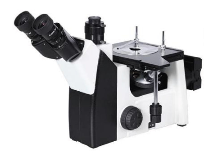
Inverted metallurgical microscopy is an optical imaging technique designed mainly for examining opaque materials such as metals, alloys, ceramics, coatings, composites, and polished engineering samples. Unlike a conventional upright microscope, the objective lenses are positioned below the sample, while the specimen is placed on a stage with its examined surface facing downward.
This configuration is particularly suitable for large, heavy, or irregular metallic specimens and provides clear reflected-light images of surface features and microstructures.
Key Applications in Metals and Materials Research:
- Examination of cracks, pores, pits, scratches, and other surface defects.
- Evaluation of metallic microstructures after polishing and chemical etching.
- Inspection of grain boundaries, phases, inclusions, and precipitates.
- Analysis of weld zones, heat-affected zones, and base metals.
- Assessment of corrosion damage and localized corrosion features.
- Examination of coatings, deposited layers, and surface treatments.
- Quality control of metallic components and manufactured parts.
- Initial inspection before advanced analysis using SEM, EDS, or other techniques.
2. Principle of Operation (Simplified)
- Step 1: Light from an LED or halogen source is directed through the objective lens toward the polished or exposed sample surface.
- Step 2: The incident light interacts with the material surface and is reflected differently depending on the surface topography, phases, grain orientation, and defects.
- Step 3: The reflected light is collected by the objective lens.
- Step 4: The image is magnified through the microscope optics.
- Step 5: The microstructure or surface defect is observed through the eyepiece and/or captured using a digital camera.
- Step 6: Images may be measured and analyzed using image-analysis software.
Because metallic samples are generally opaque, inverted metallurgical microscopy normally operates using reflected-light illumination.
Modes of Operation:
- Brightfield: The most commonly used mode. Flat and highly reflective areas appear bright, while cracks, pores, grain boundaries, and rough areas may appear darker.
- Darkfield: Highlights scratches, cracks, edges, particles, and surface irregularities against a dark background.
- Polarized Light: Useful for examining anisotropic materials, certain minerals, coatings, crystals, and stress-related features.
- Differential Interference Contrast, if available: Enhances small differences in surface height and produces a three-dimensional-like appearance.
- Digital Image Analysis: Used to measure crack length, pore dimensions, grain size, coating thickness, and area percentage of different phases.
3. Information You Will Receive in Your Report
- Digital Micrographs: High-resolution images at selected magnifications.
- Scale Bar: A calibrated scale bar included on each image.
- Magnification Details: The objective magnification and total magnification used during imaging.
- Imaging Mode: Brightfield, darkfield, polarized light, or another available mode.
- Defect Identification: Observation of visible cracks, pores, pits, inclusions, scratches, delamination, or coating defects.
- Microstructural Description: A brief description of grains, phases, grain boundaries, inclusions, or heat-affected regions.
- Dimensional Measurements: Crack length and width, pore diameter, coating thickness, grain size, or defect area when requested and technically measurable.
- Image-Processing Details: Any contrast adjustment, thresholding, stitching, or measurement procedure applied to the images.
- Observation Report: A concise interpretation of the visible features.
Example Observation:
A surface crack approximately 420 µm in length was observed. The crack was accompanied by several small pores and localized surface oxidation. The crack width varied along its length and was greater near the central region.
4. Sample Preparation Guide
Sample TypePreparation MethodMetallic Surface for Crack InspectionClean the surface carefully to remove oil, dust, corrosion products, and loose particles. Avoid grinding if the original crack morphology must be preserved.Metal or Alloy for Microstructure AnalysisCut, mount if necessary, grind, polish to a mirror-like finish, and chemically etch using a suitable etchant.Welded SamplePrepare a cross-section containing the weld metal, heat-affected zone, and base metal. Grind, polish, and etch as required.Coated MetalPrepare the surface for top-view analysis or prepare a polished cross-section for coating-thickness measurement.Corroded SampleRemove loose contaminants carefully without destroying pits or corrosion features. Do not aggressively polish unless cross-sectional analysis is required.Ceramic or CompositePrepare a flat, polished surface. Mounting may be needed for fragile or irregular samples.Large Metallic ComponentSelect a flat region that can be positioned securely on the microscope stage. A smaller representative section may be required.Powder or Metallic ParticlesDisperse a small amount on a clean glass slide or suitable holder. Particle dimensions must be within the optical resolution range.
Typical Metallographic Preparation Steps:
- Representative sample cutting.
- Mounting, when required.
- Grinding using progressively finer abrasive papers.
- Polishing using suitable diamond or oxide suspensions.
- Cleaning and drying.
- Chemical or electrolytic etching using an appropriate reagent.
- Immediate microscopic examination.
Important Notes:
- The examined surface should be flat whenever accurate measurements are required.
- A polished surface is essential for reliable metallographic analysis.
- Etching conditions depend on the type of metal or alloy.
- Excessive etching may obscure fine microstructural features.
- Crack samples should not be polished before top-surface inspection unless specifically requested.
- The submitted sample must fit safely on the microscope stage.
- The sample surface should face downward because the objective lenses are located below the specimen.
5. Understanding Your Results
Guide to Interpretation
Surface Cracks
Cracks normally appear as dark, narrow, irregular, branched, or continuous lines. Their appearance depends on illumination, surface preparation, crack opening, oxidation, and material reflectivity.
The microscope may be used to estimate:
- Crack length.
- Visible crack width.
- Crack direction and branching.
- Crack density.
- Relationship between cracks and pores, inclusions, coatings, or grain boundaries.
Optical microscopy shows only the visible surface or prepared cross-section. It cannot determine the full internal depth of a crack unless a suitable cross-section is prepared.
Grain Structure
After correct polishing and etching, grain boundaries become visible. Grain size and morphology may indicate:
- Solidification conditions.
- Heat-treatment effects.
- Recrystallization.
- Grain growth.
- Mechanical deformation.
- Differences between weld metal, heat-affected zones, and base metal.
Phases and Inclusions
Different phases may appear with different brightness, colors, or contrast. However, optical appearance alone is usually insufficient for definitive chemical identification.
SEM-EDS, XRD, or other compositional techniques may be required to confirm the identity of phases or inclusions.
Porosity and Pitting
Pores and corrosion pits generally appear as dark, rounded, irregular, or cavity-like features. Image-analysis software may be used to estimate:
- Pore size.
- Pit diameter.
- Number of pores.
- Area percentage of porosity.
- Spatial distribution of defects.
Coatings and Layers
Cross-sectional images can be used to examine:
- Coating thickness.
- Layer uniformity.
- Interface quality.
- Delamination.
- Cracks within the coating.
- Voids between the coating and substrate.
- Diffusion or reaction zones.
Welded Materials
Metallographic images may reveal differences between:
- Weld metal.
- Fusion boundary.
- Heat-affected zone.
- Base metal.
- Porosity.
- Solidification cracks.
- Lack-of-fusion regions visible in the prepared section.
- Changes in grain size and morphology.
6. Spatial Resolution and Magnification
Spatial Resolution
The practical lateral resolution of a conventional reflected-light metallurgical microscope is generally approximately 0.2–0.5 µm, depending on the objective lens, numerical aperture, illumination, sample preparation, and imaging conditions.
Fine nanoscale cracks, nanoparticles, and features smaller than the optical resolution limit cannot be resolved reliably.
Magnification
Common imaging magnifications may include:
The selected magnification depends on the size of the crack, grain, pore, inclusion, coating, or other feature of interest.
Magnification alone does not guarantee additional detail. Beyond the microscope’s resolution limit, increasing magnification produces empty magnification without revealing new structural information.
7. Limitations
- Internal cracks cannot be detected unless they reach the surface or are exposed through sectioning.
- Crack depth cannot normally be measured from a single top-view optical image.
- Features below approximately 0.2 µm cannot be resolved reliably.
- Individual nanoparticles cannot generally be observed.
- Chemical composition cannot be identified directly.
- Accurate grain-size analysis requires proper polishing and etching.
- Rough, curved, or highly irregular surfaces may produce blurred or uneven images.
- Transparent or semi-transparent coatings may require special illumination and careful interpretation.
- Optical microscopy cannot replace non-destructive techniques for detecting deeply embedded defects.
For smaller features, detailed fracture morphology, nanoscale cracks, or elemental analysis, SEM and EDS are recommended.
8. Frequently Asked Questions (FAQ)
What materials can be examined?
Metals, alloys, welded samples, coatings, ceramics, composites, polished sections, corroded materials, and many other opaque engineering materials can be examined.
Can the microscope detect cracks?
Yes. Surface cracks and cracks exposed in a prepared cross-section can be visualized and measured when they are larger than the microscope’s resolution limit.
Can crack depth be measured?
Not directly from a standard top-view image. Crack depth requires cross-sectional preparation, serial sectioning, profilometry, confocal microscopy, SEM, or another suitable method.
Can crack width and length be measured?
Yes, provided the crack is clearly visible, properly focused, and larger than the resolution limit. Measurements are performed using calibrated image-analysis software.
Can grain size be measured?
Yes. The sample must be correctly polished and etched. Grain size may be evaluated using standardized line-intercept, planimetric, or image-analysis methods.
Can coating thickness be measured?
Yes. A polished cross-section perpendicular to the coating surface is normally required.
Can porosity be measured?
Yes. Visible pore size, pore number, and area percentage may be estimated using calibrated image analysis.
Can the microscope identify the chemical composition of inclusions?
No. Optical microscopy can show differences in appearance, but chemical identification usually requires SEM-EDS or another analytical technique.
What is the maximum magnification?
The practical maximum is typically approximately 1000× to 1500×, depending on the available objectives and optical system.
How much sample is required?
A small representative section is generally sufficient. The sample must fit securely on the microscope stage and present a suitable flat examination surface.
How long does the analysis take?
Basic imaging may require approximately 1–2 hours after receiving a properly prepared sample. Additional time may be required for cutting, mounting, grinding, polishing, etching, image stitching, or quantitative measurements.
9. Recommended Complementary Analyses
Depending on the objective of the study, inverted metallurgical microscopy may be combined with:
- Scanning Electron Microscopy: For high-resolution crack and fracture-surface examination.
- EDS Analysis: For elemental composition of inclusions, corrosion products, or phases.
- X-ray Diffraction: For crystalline-phase identification.
- Surface Profilometry: For crack depth, roughness, and surface-height measurements.
- Microhardness Testing: For evaluating hardness variations across welds, coatings, and heat-affected zones.
- Ultrasonic Testing: For detecting internal defects and subsurface cracks.
- Dye-Penetrant Testing: For non-destructive detection of surface-breaking cracks.
- Magnetic-Particle Testing: For surface and near-surface cracks in ferromagnetic materials.
- Atomic Force Microscopy: For nanoscale surface-topography analysis.
10. References
- [1] Vander Voort, G. F. (1999). Metallography: Principles and Practice. ASM International.
- [2] ASTM International. ASTM E3: Standard Guide for Preparation of Metallographic Specimens.
- [3] ASTM International. ASTM E407: Standard Practice for Microetching Metals and Alloys.
- [4] ASTM International. ASTM E112: Standard Test Methods for Determining Average Grain Size.
- [5] ASM International. ASM Handbook, Volume 9: Metallography and Microstructures.
- Internal Source: Phi Nanoscience Center provides inverted metallurgical microscopy for surface inspection, metallographic analysis, crack evaluation, coating examination, and quality control of metallic and engineering materials.
11. Request This Test
To request Inverted Metallurgical Microscopy analysis or any of our other services, please complete the Sample Testing Request Form.